

Hey there! As a supplier of RTD PT200 Probes, I get a ton of questions about how to connect these probes to a microcontroller. It's a crucial step for many projects, whether you're working on industrial monitoring, environmental sensing, or any other application that requires accurate temperature measurement. So, in this blog post, I'm gonna walk you through the process step by step.
Understanding the RTD PT200 Probe
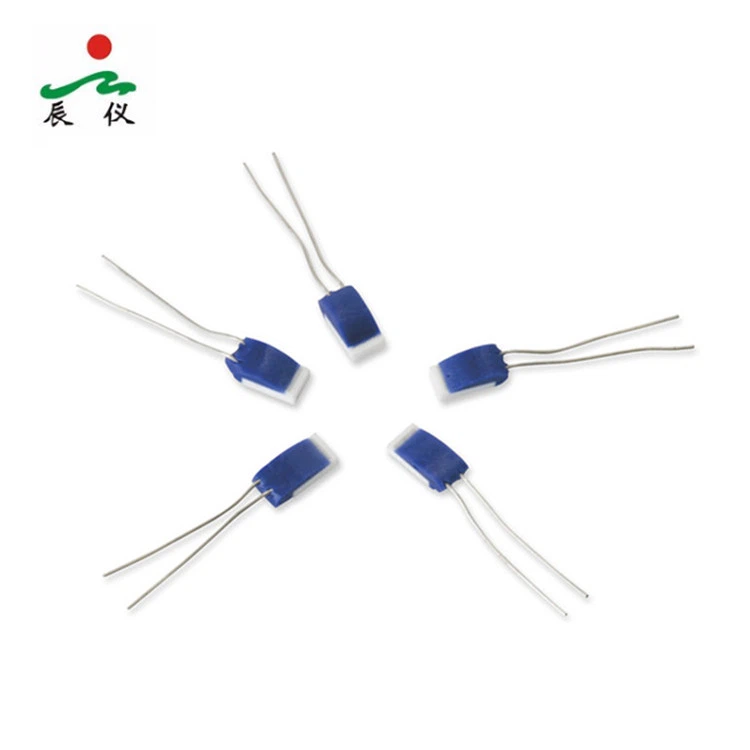
First things first, let's talk a bit about what an RTD PT200 Probe is. RTD stands for Resistance Temperature Detector, and it's a type of temperature sensor that works based on the principle that the electrical resistance of a metal changes with temperature. The "PT" in PT200 indicates that it's made of platinum, which is a popular choice for RTDs because of its high accuracy, stability, and linearity. The "200" refers to the resistance of the probe at 0°C, which is 200 ohms.
These probes are often used in applications where precise temperature measurement is required, such as in the food industry, pharmaceuticals, and HVAC systems. They come in different shapes and sizes, and can have different numbers of wires depending on the application.
Why Connect to a Microcontroller?
Connecting an RTD PT200 Probe to a microcontroller allows you to collect temperature data and use it for various purposes. You can display the temperature on a screen, log it for later analysis, or use it to control other devices. Microcontrollers are small, low - cost, and easy to program, making them a great choice for integrating with RTD probes.
Prerequisites
Before you start connecting the RTD PT200 Probe to the microcontroller, you'll need a few things:
- An RTD PT200 Probe: Obviously, you can get one from us as a supplier.
- A microcontroller: Popular choices include Arduino, Raspberry Pi, or PIC microcontrollers.
- A signal conditioning circuit: Since the output of the RTD is a change in resistance, you'll need a circuit to convert this into a voltage that the microcontroller can read.
- Wires and connectors: To make the electrical connections.
Step 1: Signal Conditioning
The first step is to condition the signal from the RTD PT200 Probe. As I mentioned earlier, the probe outputs a change in resistance, but most microcontrollers can only read voltage signals. So, you need to convert the resistance change into a voltage change.

One common way to do this is by using a Wheatstone bridge circuit. A Wheatstone bridge consists of four resistors, with the RTD PT200 Probe being one of them. When the temperature changes, the resistance of the RTD changes, which causes an imbalance in the bridge. This imbalance results in a small voltage difference across the bridge, which can be amplified using an operational amplifier (op - amp).
There are also integrated circuits available that can do the signal conditioning for you. These chips are designed specifically for RTD sensors and can simplify the process significantly.
Step 2: Connecting the Signal Conditioning Circuit to the Microcontroller
Once you have the conditioned voltage signal, you need to connect it to the microcontroller. Most microcontrollers have analog input pins that can read the voltage.
- Identify the analog input pin on your microcontroller. For example, on an Arduino Uno, pins A0 - A5 are analog input pins.
- Connect the output of the signal conditioning circuit to the analog input pin using a wire. Make sure to use proper insulation and secure the connection to avoid any loose wires.
Step 3: Powering the Circuit
The RTD PT200 Probe and the signal conditioning circuit need power to work.
- Check the power requirements of your RTD PT200 Probe and the signal conditioning circuit. Most RTDs can operate with a low - voltage power supply, typically between 5V and 12V.
- Connect the power supply to the appropriate pins on the RTD and the signal conditioning circuit. Make sure to connect the positive and negative terminals correctly to avoid damaging the components.
Step 4: Programming the Microcontroller
Now that the hardware is connected, you need to program the microcontroller to read the temperature data.
- If you're using an Arduino, you can use the built - in analogRead() function to read the voltage from the analog input pin.
- You'll need to convert the voltage reading into a temperature value. This can be done using the calibration equation for the RTD PT200 Probe. The calibration equation relates the resistance of the RTD to the temperature. Since you've converted the resistance to voltage, you'll need to do a bit of math to get the temperature.
Here's a simple example of Arduino code to read the voltage and print it to the serial monitor:
const int analogPin = A0;

void setup() {
  Serial.begin(9600);
}

void loop() {
  int sensorValue = analogRead(analogPin);
  Serial.print("Sensor Value: ");
  Serial.println(sensorValue);
  delay(1000);
}
Different Types of RTD Probes and Their Considerations
There are other types of RTD probes available, such as the Thin Film Element, 6 Wire Pt100 RTD, and Pt100 Surface RTD.
- Thin Film Element: These probes are very accurate and have a fast response time. However, they can be more fragile compared to other types. When connecting them to a microcontroller, you need to be extra careful with the signal conditioning to ensure accurate readings.
- 6 Wire Pt100 RTD: The 6 - wire configuration helps to reduce the effects of lead resistance, which can improve the accuracy of the temperature measurement. The connection process is similar to the PT200 Probe, but you'll need to pay attention to the additional wires.
- Pt100 Surface RTD: These probes are designed to measure the surface temperature. They can be used in applications where you need to monitor the temperature of a specific surface. The connection and programming steps are similar to the PT200 Probe, but you may need to adjust the calibration based on the specific characteristics of the Pt100 Surface RTD.
Troubleshooting
If you're having trouble getting accurate temperature readings or if the microcontroller isn't reading the signal correctly, here are some things to check:
- Connection: Make sure all the wires are properly connected and there are no loose connections. A loose wire can cause intermittent or incorrect readings.
- Power Supply: Check that the power supply is providing the correct voltage and that the positive and negative terminals are connected correctly.
- Signal Conditioning: If the signal conditioning circuit is not working properly, it can affect the accuracy of the readings. Check the components in the circuit for any signs of damage or incorrect values.
Conclusion
Connecting an RTD PT200 Probe to a microcontroller is a great way to collect and use temperature data in your projects. By following the steps outlined in this blog post, you should be able to get your system up and running in no time.
If you're interested in purchasing RTD PT200 Probes or have any questions about the connection process, feel free to reach out to us. We're here to help you with all your RTD needs.
References
- "Temperature Measurement with RTD Sensors" by Analog Devices
- "Arduino Reference Manual" by Arduino
- "RTD Sensor Application Notes" by Texas Instruments
